FX40 with monitor

Scanning ElectroChemical Cell Microscopy (SECCM)

Scanning probe microscopy (SPM), and especially pipette-based SPM techniques can offer new insights into the nano-scale chemical properties of the sample. Among the pipette-based SPM techniques, Scanning electrochemical cell microscopy (SECCM) is a recently developed pipette-based SPM technique designed to investigate the local electrochemical properties of surfaces. Using laser-pulled pipettes with nano or microscale tip radius, SECCM allows investigating electrochemical responses on target materials by applying a bias sweep, also known as cyclic voltammetry (CV).

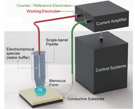
Scanning probe microscopy (SPM), and especially pipette-based SPM techniques can offer new insights into the nano-scale chemical properties of the sample. Among the pipette-based SPM techniques, Scanning electrochemical cell microscopy (SECCM) is a recently developed pipette-based SPM technique designed to investigate the local electrochemical properties of surfaces. Using laser-pulled pipettes with nano or microscale tip radius, SECCM allows investigating electrochemical responses on target materials by applying a bias sweep, also known as cyclic voltammetry (CV). Unlike other pipettebased SPM techniques such as Scanning ion conductance microscopy (SICM) or Scanning electrochemical microscopy (SECM), SECCM is not conducted with the nanopipette fully submerged in the solution. Instead, it utilizes an electrolyte-filled nano-pipette to establish a meniscus contact between pipette and the sample surface. This meniscus acts as an electrochemical cell enabling local measurements in ambient conditions. Here, the response area, e.g. the size of the electrochemical cell, can be controlled with the size of the inner diameter of the nano-pipette. In literature, two main pipette designs can be distinguished: a single barrel pipette with a separate reference electrode and a double- barrel pipette with an integrated counter electrode. In this note, we present a singlebarrel approach of a SECCM measurement conducted with Park systems’ AFM, as depicted in figure 1.
seccm

Figure 1. Graphic design of SECCM

seccm

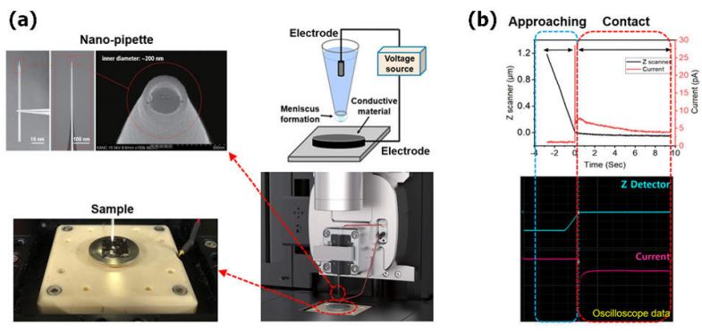
Figure 2. (a) SECCM operation set-up with nano-pipette and sample, (b) current response on approaching and contact.

Here, a nano-pipette is filled with an electrolyte and an electrochemical species, acting as a scanning probe (figure 2 (a)). The nano-pipettes are made from commercial glass capillaries or quartz capillaries that are heated and subsequently pulled using a so-called pipette puller. The resulting inner diameter of the pipette is determined by the length, the glass capillaries’ outer and inner diameter, the wall thickness, and the puller parameters. Here, prudent pipette characterization is essential, since the spatial resolution and electrochemical signal depend on the size of the inner diameter of the nanopipette. To detect the electrochemical signal, an electrode is inserted into the back end of the nano-pipette and a bias is applied between the nano-pipette tip and the surface. Once the nano-pipette approaches the sample surface, a meniscus is formed, establishing a flow of current (figure 2 (b)). Initially, the current peaks due to migrating ions within the electrochemical cell and charging effects for example due to the formation of a double layer at the interfaces. However, the current decreases with a decreasing distance of pipette tip and surface due to space-limited diffusion of migration ions. The system detects the respective change in current and adjusts the Z scanner movement accordingly. Electrochemical species in the confined meniscus undergo an electrochemical reaction when a specific bias is applied between the nano-pipette electrode and the working electrode placed on the XY scanner. The approach-retract scanning (ARS) method represents one option to visualize the electrochemical response of the sample. Here, the pipette linearly approaches and retracts repeatedly from the sample surface while monitoring the current signal of every single pixel. Thus, at each pixel, an independent CV curve is measured which can be used to create an electrochemical response image of a specific area.

seccm

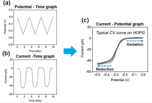
Figure 3. CV measurement; Graph of (a) potential vs. time, (b) current vs. time, and (c) current vs. potential.

For that, the potential of the working electrode is scanned in one direction and subsequently reversed to return to the initial potential (figure 3) while the change of the current signal is recorded to obtain a CV curve. However, the measured current is not only determined by the applied potential but also influenced by the scan rate, electrochemical species concentration, and ionic strength of the supporting electrolyte. Therefore, measurement parameters should be selected appropriately so that the oxidation/reduction signal of the substance of interest can be observed.

seccm

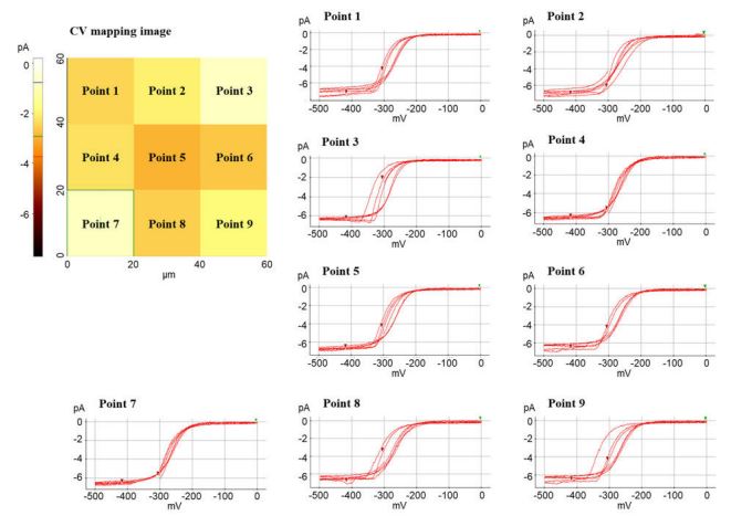
Figure 4. CV mapping image with each CV curve on HOPG surface.

Figure 4 shows a representative example of a CV mapping image by ARS mode for which CV curves were recorded at an array of 3 × 3 pixels on a HOPG surface. For that, a pipette was used with a 200 nm inner diameter, with a 100 mM KCl solution as the supporting electrolyte and a concentration of 10 mM Ru(NH3)6 Cl3 as the electrochemical species, while measuring at a 1 V/s scan rate. The smooth sigmoidal wave shape observed is characteristic of the CV acquired in SECCM format. This sigmoidal plot corresponds to a steady-state voltammogram, and the limit current was approximately -6.5 pA at a sample bias of -0.5 V. Here, [Ru(NH3)6]3+ is reduced when applying a potential of 0 V to -0.5 V, and accordingly, an oxidation reaction occurs at a potential of 0 V to -0.5 V. As expected for a homogeneous HOPG substrate, the shape and limit current values of the CV curves exhibit similar characteristics. Accordingly, samples with varying electrochemical surface properties will exhibit a respective EC signal contrast.